March 2004
In this issue:
- Operational Definitions: The Key to Getting Good Data
- Evaluating the Measurement Process Using Control Charts
- Quick Links
The focus for this month is on operational definitions. Operational definitions are one key to good data collection. They are a necessary, although not sufficient, condition for good data collection. Plus, we will look at how control charts can be used to evaluate the measurement system.
Operational Definitions: The Key to Getting Good Data

“Finished files are the result of years of scientific study combined with the experience of years.”
Now ask several other people to count the number of “f’s.” Did they all get the same result as you? How many f’s are there? It depends on the operational definition of “f”. If the operational definition is any “f”, there are a total of six. If the operational definition is only upper case f’s, then there is only one. If the operational definition is only lower case f’s, then there are five. So, the answer depends on what the operational definition is.
What is an operational definition?
An operational definition is a clear, concise, detailed definition of a measure. You need operational definitions when collecting all types of data. It is particularly important when a decision is being made about whether something is defective or not defective or whether a defect exists or not. For example, how do you know if a shipment is on time or not on time? The data collection will be meaningless if the definition of on time has not been specified. Thus, operational definitions should be developed and tested before the data collection begins.
How is an operational definition developed?
The six steps in developing operational definitions are given below.
1. Identify the characteristic you are interested in.
In this step, simply identify the characteristic you want to measure. For example, you might want to measure the picking accuracy for a picker in a warehouse. A pick ticket is printed in a warehouse listing the line items to be picked as well as the quantity of each line item to pick. A picker uses this pick ticket to pick the items from the shelves in the warehouse.
Example: Daily Picking Accuracy
2. Select the measuring instrument.
The measuring instrument is either a physical piece of measuring equipment (such as a micrometer, scale, hardness tester, tensile tester or a clock) or a visual check. You may want to include standards if you are doing a visual check. For example, you may be judging the color of a product. You should include standards that show the acceptable color range.
Example: A visual inspection of the items picked and quantity picked is the measuring instrument for picking accuracy.
3. Describe the test method and/or criteria.
If the measuring equipment is a physical piece of measuring equipment, the test method is simply the procedure for taking the measurement. The degree of accuracy needs to be stated. For example, if you are measuring how long something takes, are you measuring in seconds, minutes, 15-minute intervals, etc.? Visual checks also require criteria.
Example: The picker takes the order to a packing table. For each line item on the pick ticket, the packer compares the line item description to the item picked by the picker. If the line item description matches the line item picked, the correct line item was picked. The packer then counts the quantity picked for that line item and compares that to the quantity listed on the pick ticket. If the quantities match, the correct quantity was picked. If both the correct item and the correct quantity were picked, the line item was picked accurately. If either is incorrect, the line item was not picked accurately. For each order, the picker records the number of line items picked correctly and the total number of line items picked.
4. Perform the test and reach a decision
In this step the test is performed and a decision is reached. Does the item meet the criteria? Does a problem exist?
Example: To determine the daily picking accuracy, the picker counts up the number of line items picked correctly (np) and the total number of line items picked (n) for the day. The daily picking accuracy is determined by dividing np by n and multiplying by 100 to convert to a percentage. If the picking accuracy is 100%, no picking errors were made for the day.
5. Document the Operational Definition
Write down the information in steps 1 through 4. The operational definition should be included in all training materials and standard operating procedures.
6. Test the operational definition.
Before implementing the operational definition, test it out on a small scale. In the example above, you can ask several pickers to take data for a week. They probably will have input on how to improve the operational definition. Check their results. Were they correct?
Dr. W. Edwards Deming said, “An operational definition is one that people can do business with…. It must be communicable, with the same meaning to vendor as to purchaser, same meaning yesterday and today.” A good operational definition enables everyone in the process to use and understand the term exactly the same way each time.
In the picking example above, you could monitor the results using a p control chart. However, you would also want to take data on reasons for picking errors. You will need operational definitions for the various reasons. The errors could then be tracked using a Pareto diagram. The errors that occur most frequently should be worked on first.
Evaluating the Measurement Process Using Control Charts

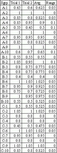
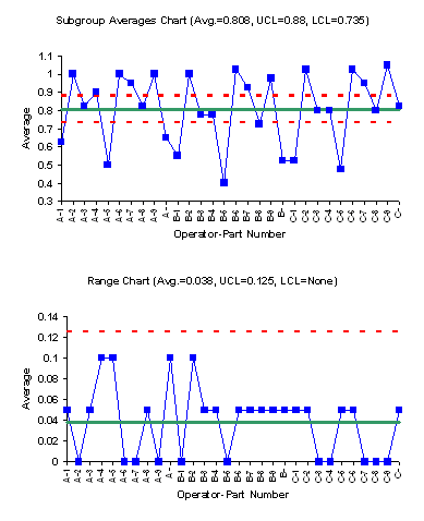
The ranges are plotted on the range chart. The range for each subgroup is the difference between two measurements made by the same operator on the same part. This chart gives us the test-retest error. It should be small if the measurement process is capable of distinguishing between the samples from the process. The first step is to calculate the average range and the control limits for the range chart. The subgroup ranges are plotted on the range chart along with the average range and the control limits. The range chart is the second chart shown below.
The range chart is in statistical control. This means that the operators have the same test-retest error.
The subgroup averages are plotted on a separate chart. The first step is to calculate the overall average and the control limits. The subgroup averages, the average, and the control limits are then plotted on the subgroup averages chart. This is the top chart shown below.
This chart has most of the points out of control. This is what you hope to see. It means that the measurement process is capable of distinguishing between the samples. Remember that the average range is based on the test-retest error. If the measurement process is a “good” process, the test- retest error should be much smaller than the variation between the parts. The subgroup averages chart above confirms this.
So, you can use control charts to determine if the measurement system is capable of distinguishing between samples from your process. Control charts can also be used to examine operator bias and consistency in the study done above. The SPC for MS Excel program contains the Gage R&R/Measurement Systems Analysis tools including the Gage R&R classic report, charts for operator bias and consistency as well as charts for each operator in the study.
